Normally Open Auxiliary Contact Symbol

Basic Switch No Nc And Com Contact Terminal Faq Australia Omron Ia
Devices Symbols And Circuits Electrical Circuits Electric Equipment

Industrial Electronics Troubleshooting Devices Symbols And Circuits

Contact Types Normally Open And Normally Closed Wiki Product Faqs

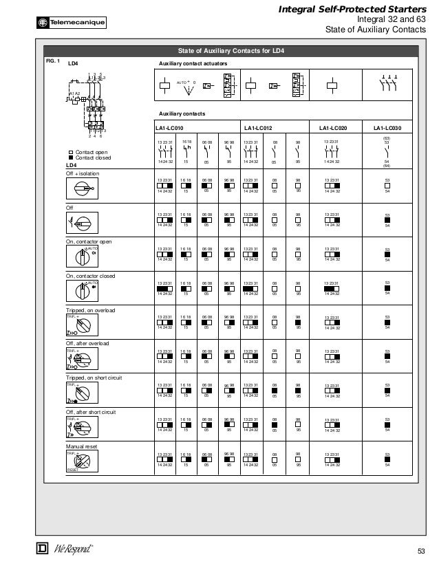
Nema And Iec Terminal Markings
All About Automation 2011
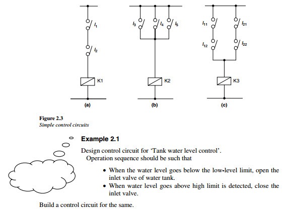
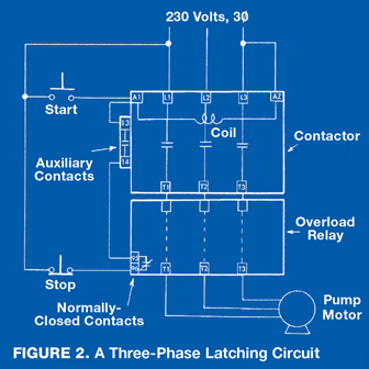
A limiting condition is wired through the coil contacts and resulting conditions are wired through the.
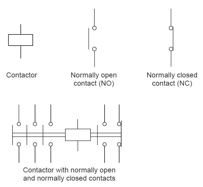
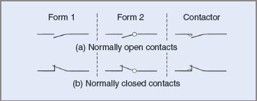
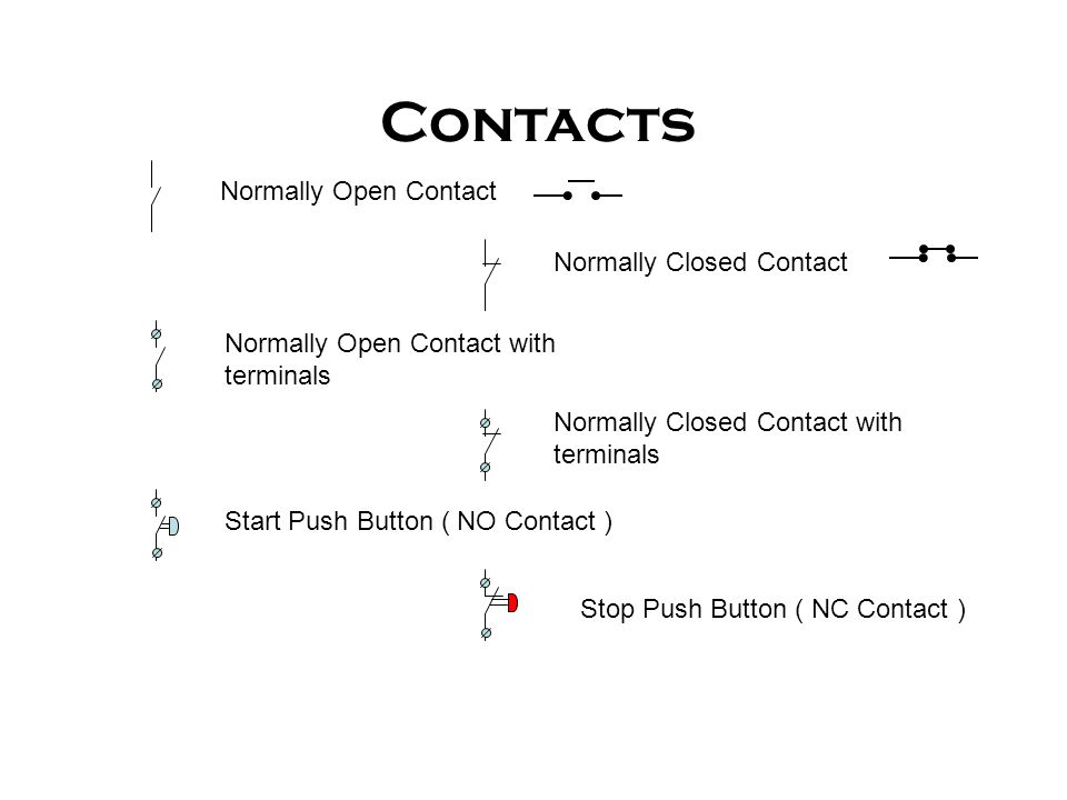
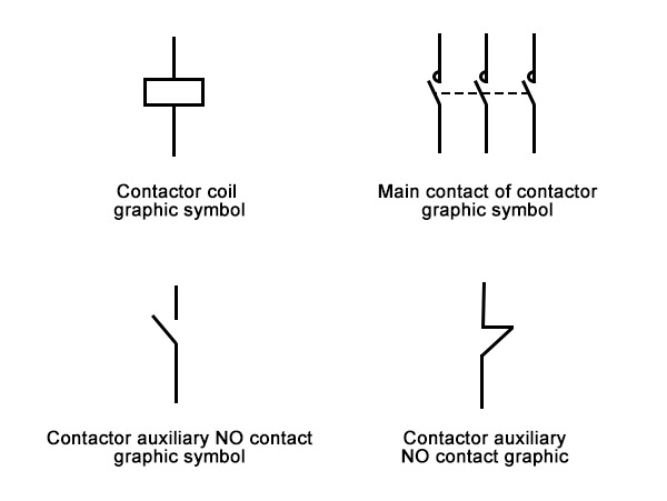
Normally open auxiliary contact symbol.
Electrical Control Relay Tutorial
Contactors And Relays Construction Operation

Overload Relays Contactors Overloads Product Guides
Elec Machine

Auxilliary Contacts Electra Cloud Symbols
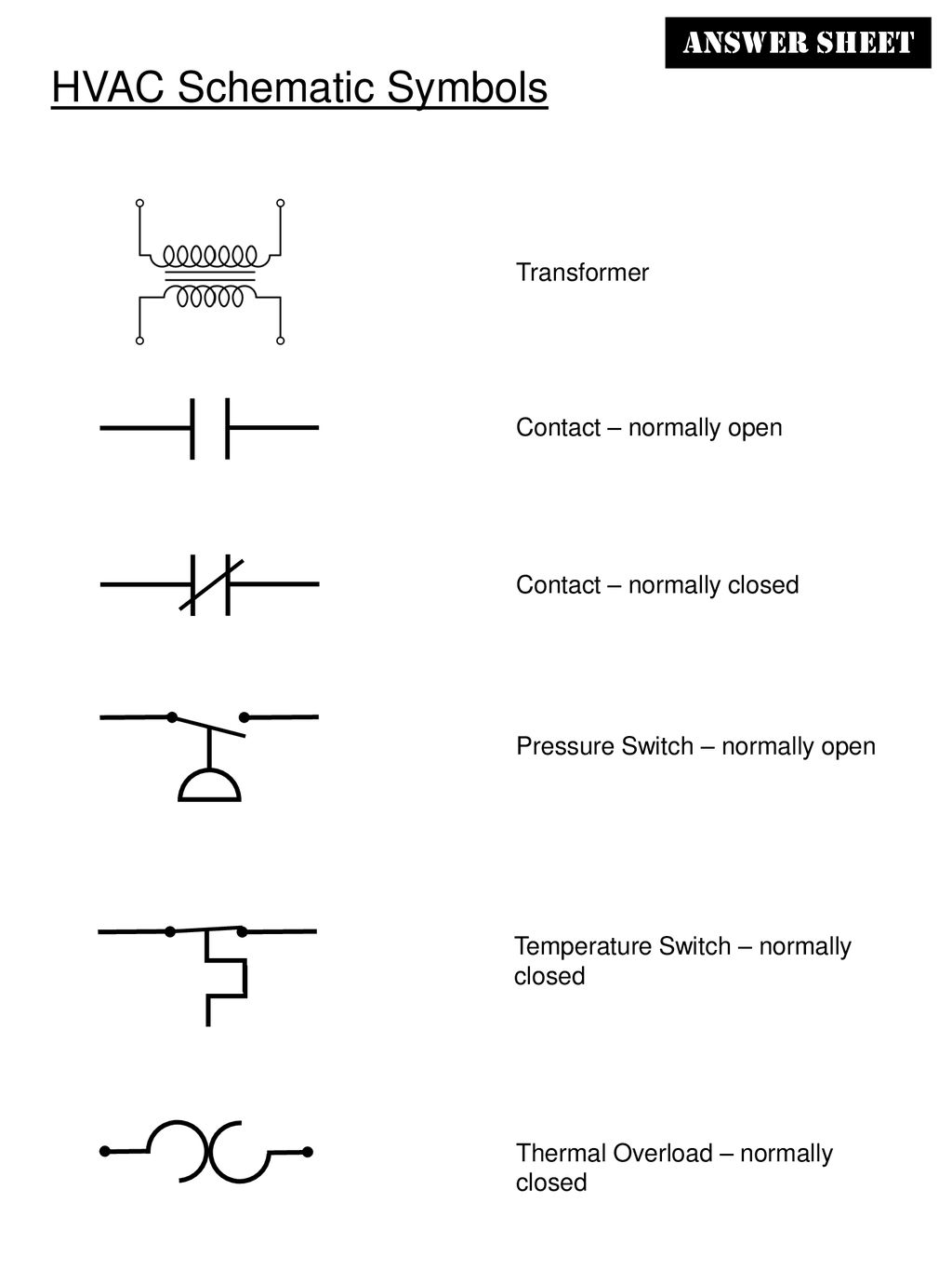
Hvac Schematic Symbols Ppt Download
Components Symbols Used In Electrical Circuits Ppt Download

Basic Principles Of Automatic Motor Control
What Are The Commonly Used Electrical Components In The Distribution Cabinet Quisure

Limit Switches
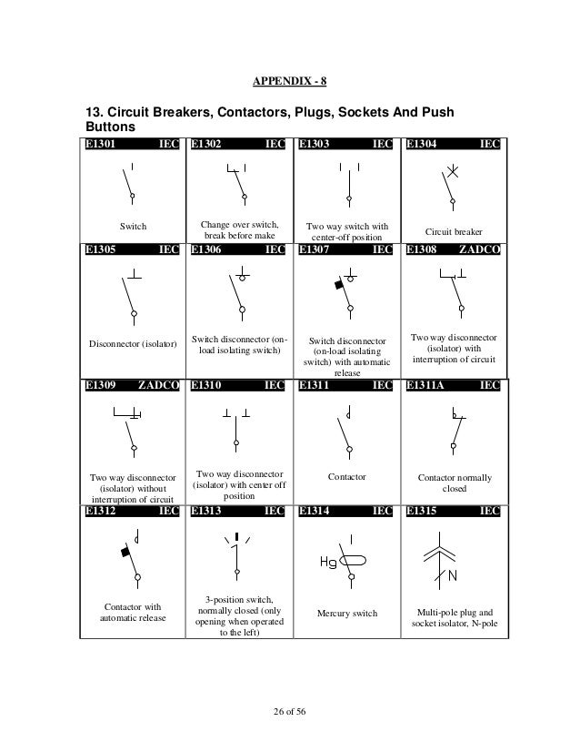
Iec Symbol Reference

Auxiliary Contacts Internal Structure Diagram Auxiliary Electrical Engineering Engineering
Service Technician Training Electricity For Servicepeople Part 22 Cleaner Times

Pdf Motor Control Basics Pdf Dominic Jay Sunga Academia Edu
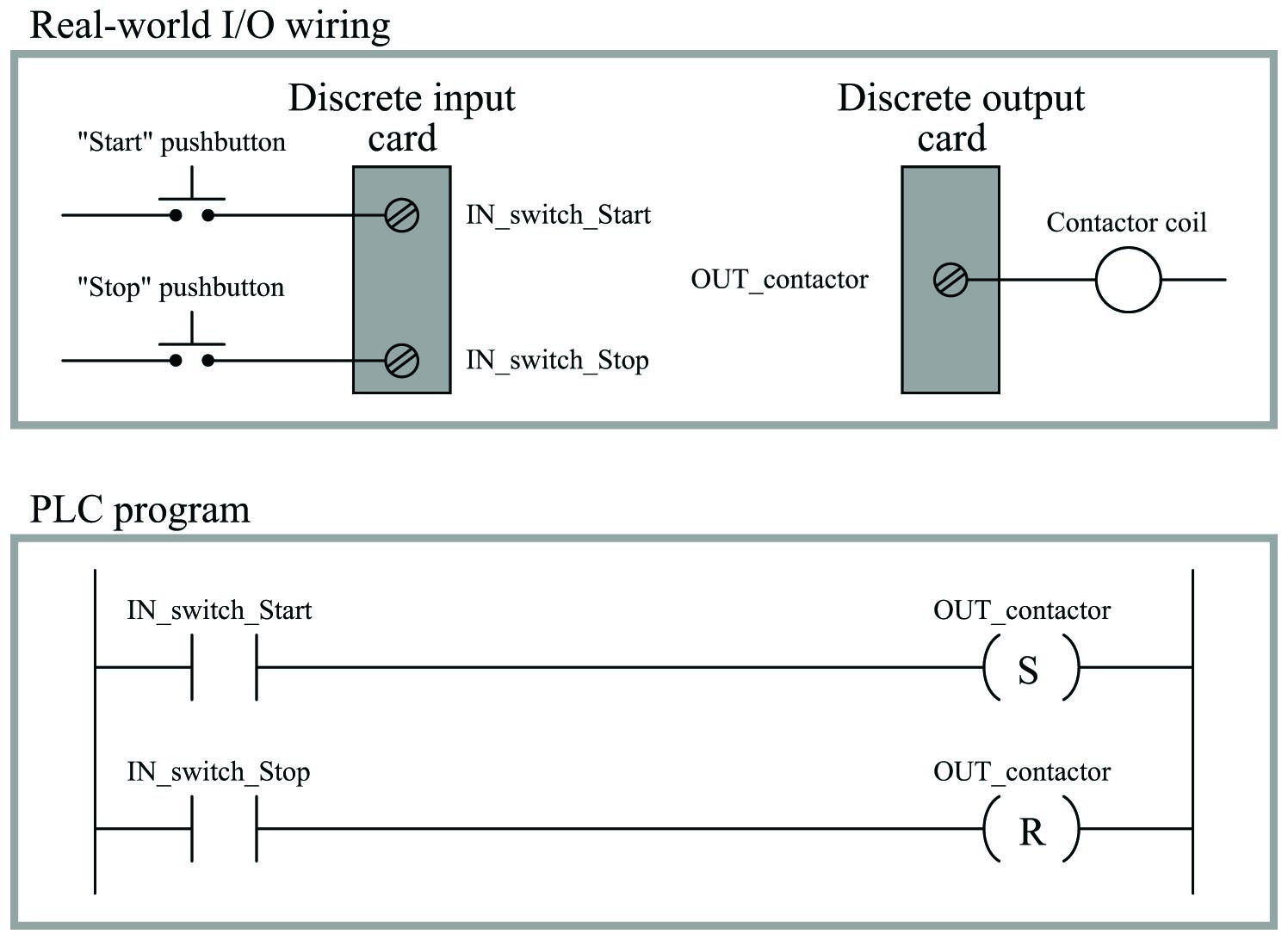
Ladder Diagram Ld Programming Basics Of Programmable Logic Controllers Plcs Automation Textbook

Control Circuits Schematic Diagrams Wiring Diagrams And Reading Schematic Diagrams Hvac Machinery
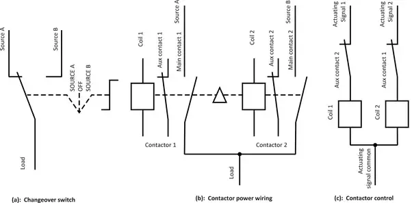
What Is The Difference Between The Changeover Switch And The Contactor Quora
Circuit Breaker Accessories Explained
Https Encrypted Tbn0 Gstatic Com Images Q Tbn 3aand9gcthqz7xvkvptd6qzekj4vjtvap66ypt3xj4poapek5s0 7aprid Usqp Cau

Rated Characteristics Of Electrical Contactors Electrical Technology In 2020 Electrical Circuit Diagram Basic Electrical Wiring Electrical Projects

Wiring Diagram Book File 0140 Diagram Diagramtemplate Diagramsample

Jic Nfpa Symbols

Magnetic Motor Starter Basics What It Is How It Works And More

Dol Starter Direct Online Starter Diagram Working Principle Electrical4u
Source : pinterest.com
