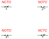
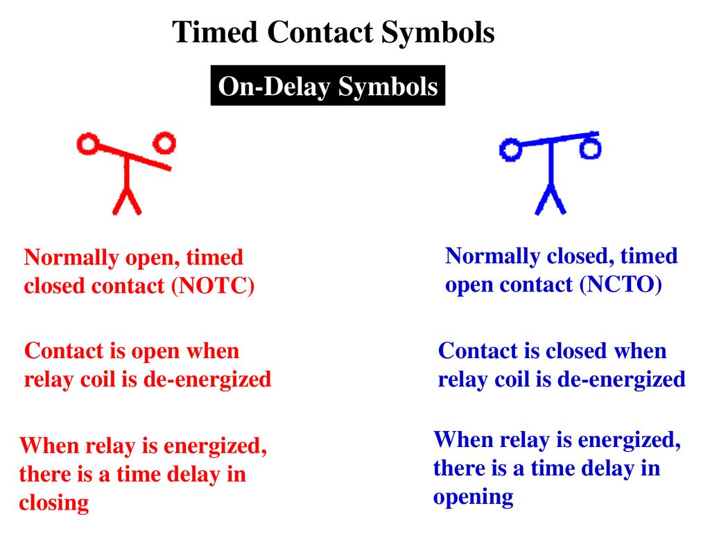
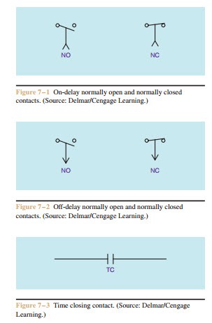
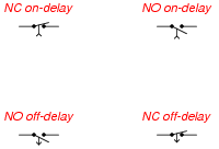
Normally Open Timed Closed Contact Symbol
Time Delay Electromechanical Relays Worksheet Digital Circuits
Programming Timers Ppt Download
Timing Relays Pneumatic Timers Electric Equipment
Time Delay Electromechanical Relays Worksheet
Programmable Logic Controllers Ppt Video Online Download

Electrical Wiring Diagram Symbols Flashcards Quizlet
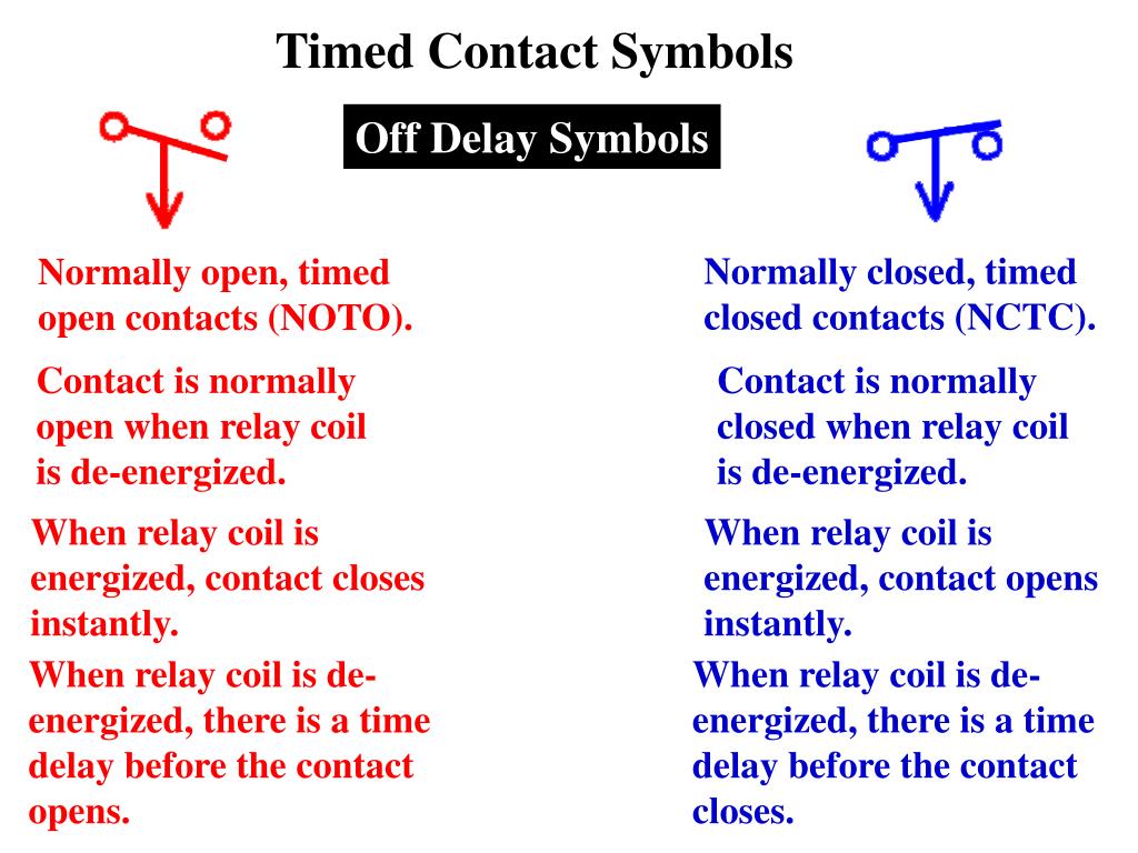
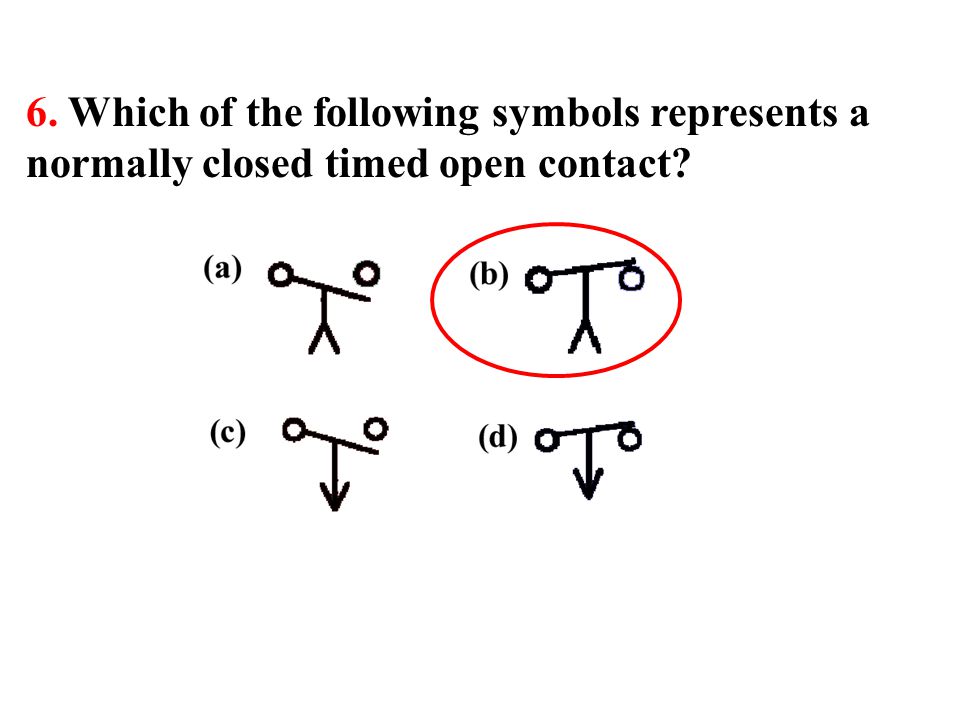
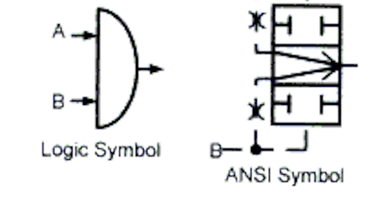
The contact is opened by applying power to the relay coil but for the specified amount of time only after the coil has been continuously powered.
Normally open timed closed contact symbol.

Industrial Timers Advanced Solid State Logic Flip Flops Shift Registers Counters And Timers
Time Delay Relay On Delay Timer Off Delay Timer Electrical Academia

Timing Relays Control Pilot Devices

Types Of Time Delay Relay Applications Of Time Delay Relay Instrumentation And Control Engineering

Industrial Motor Control Symbols And Schematic Diagrams
Ppt Programmable Logic Controllers Third Edition Powerpoint Presentation Id 4454520

Electrical Symbols For Other Pilot Devices

Chapter Ppt Download
Contactors And Relays Construction Operation

Industrial Motor Control Timing Relays

Circuit Layout Connections And Symbols Symbols

Some Lld Symbols For The Siemens S7 300 Plc Download Table
Book 2 Chapter 2 Air Logic Circuits Hydraulics Pneumatics

The Lld Symbols For Siemens S7 300 Plc Download Table
Ladder Diagram Ld Programming Basics Of Programmable Logic Controllers Plcs Automation Textbook

4th 1st Final Part I Flashcards Quizlet

Electromechanical Relay Logic Worksheet Digital Circuits
Https Svwater Com Documents 593 Svwrf Misc Electrical Upgrades Electrical Drawings Final Pdf
Https Encrypted Tbn0 Gstatic Com Images Q Tbn 3aand9gcsh1 Jo14pup3zrq6mhr9tix2rdydvigkdwsyp1s6xxrmktrr5p Usqp Cau
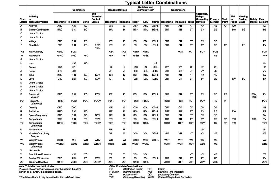
P Id Symbol Diagram Basics 3 3 Functional Identification

Homemade Electronic Circuits And Engineering Projects Electronics Projects Circuit Projects Electronics Circuit

Latch Circuits Worksheet Digital Circuits

Timers Electra Cloud Symbols

Ac Motor Control Circuits Worksheet Ac Electric Circuits
Source : pinterest.com
